An Activity Network Diagram is a diagram of project activities that shows the sequential relationships of activities using arrows and nodes. An activity network diagram tool is used extensively in and is necessary for the identification of a project’s critical path (which is used to determine the expected completion time of the project).
Example: Suppose the team is tasked with improving the process of building a house. The team lists the major steps involved – everything from the excavation step through the landscaping step.
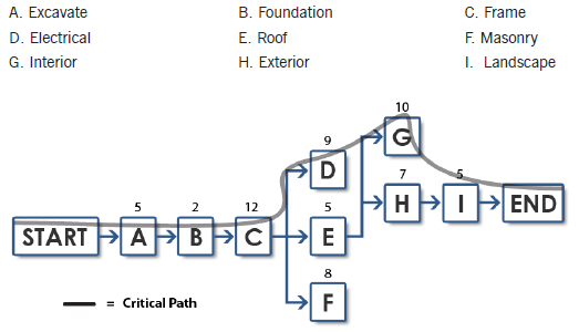
The team creates a chart – Activity Network Diagram – where the nodes (the boxes) represent the nine major steps involved in building a house. Arrows that connect the nodes show the flow of the process.
Some of the process steps (nodes A, B, and C) run in series, while other process steps (nodes D, E, and F) run in parallel. Notice that Step B cannot happen until step A has been completed. Likewise, step C cannot happen until step B has completed. Step H cannot happen until steps D, E, and F have completed – and ALL need to be completed before Step H. So, nodes A, B, and C are running in series. Nodes D, E, and F run in parallel. This is important to know because those steps that are running in parallel most likely will have different expected completion times.
Critical Path
The team’s job is to take note of which of the nodes D, E, and F, will be taking the most amount of time, and which of those nodes is expected to take the least amount of time. This is essential when creating the Critical Path. For instance, if node D is expected to take the most amount of time as compared with nodes E and F, it is not important that nodes D and E start at the exact same time as node F. Those steps can start later, but they have to be finished no later than the most time consuming of the three steps that run in parallel. The team evaluates the nine steps and come to a consensus on how many days each of the nine steps will take. The critical path is a line that goes through all of the nodes that have the longest expected completion times.
Most Likely Time
Nodes A, B, and C run in series, so the critical path is straightforward. Notice that between the three nodes that run in parallel, (nodes D, E, and F) node D is expected to take the longest to complete as compared to the other two nodes. The critical path would run through nodes D and G because those particular nodes have the longest expected completion times. The line above shows the critical path. By looking at the Activity Network Diagram the team can easily see that the expected completion time as defined by the critical path is 50 days. (5+2+12+9+10+7+5 = 50 days) That’s the MOST LIKELY time.
Optimistic Time
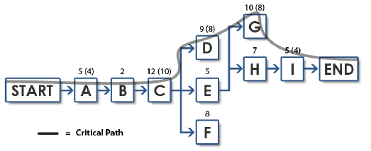
The team might want to know what the best case (Optimistic Time), in terms of time, would be. To come up with that number, the team would decide upon the shortest possible time for each of the nodes, and then add those up. The numbers in parenthesis are the most optimistic times. (4+2+10+8+8+7+4 = 43)
Pessimistic Time
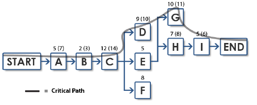
The team also might want to know what the worst case (Pessimistic Time), in terms of time, would be. To come up with that number, the team would decide upon the longest possible time for each of the nodes, and then add those up. Note: To determine the best case or the worst case, the critical path line must be followed. The numbers in parentheses are the most pessimistic times. (7+3+14+10+11+8+6 = 59) Remember, you are only calculating the numbers along the critical path when calculating the most optimistic and pessimistic times.
Expected Time
So what does all of this mean? It means the project most likely will take 50 days, but it could take 59 days, or it can be done as soon as 43 days.
Control Bands
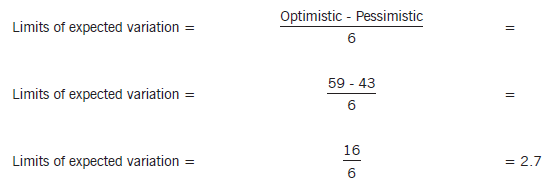
We could calculate control bands around the average. Here’s how we do that:
For the critical path, we can expect the project to take from 47.6 days to 53.0 days
50.3 + 2.7 = 53 on the high side
50.3 – 2.7 = 47.6 on the low side.


